
These instructions are for a simple 2.4 x 2.4 m, mono pitch-roofed re-locatable garden shed with plywood exterior cladding, a door and a window and no interior lining.
Contact your local council to check that the shed described here and its proposed location comply with all local planning and building rules and find out whether a building or resource consent is required prior to construction (click here to see our information on consent exemptions and building code).
Materials
| Bearers /skids | 100 x 100 mm H5 treated radiata pine timber |
| Joists | 100 x 50 mm H3.2 treated radiata pine timber |
| Floor | 18 mm construction plywood H3 treated (2.4 m x 1.2 m sheets) |
| Rafters | 140 x 45 mm H3.2 treated radiata pine timber |
| Wall frame | 90 x 45 mm H3.2 treated radiata pine timber |
| Cladding | 12 mm cladding grade construction plywood H3 treated (2.7 m x 1.2 m sheets) |
| Exterior trims | 70 x 18 mm H3.2 treated timber door architrave |
| Fascia board | 140 x 18 mm H3.2 treated timber |
| Roofing | Factory painted corrugated long-run metal roofing 2 x lengths of matched barge flashing 1 x length of soft-edged verge flashing Roofing screws for corrugated iron |
| Underlay | Heavyweight black building paper and galvanised chicken mesh |
| Nails | 100 mm jolt-head hot-dip galvanised nails 75 mm jolt-head hot-dip galvanised nails 60 mm flat-head hot-dip galvanised nails |
| Door | Pre-hung 710 mm exterior grade panel door and relevant door hardware (framing may be adjusted to suit other widths) |
| Window | 800 x 600 mm aluminium window with timber reveal (framing may be adjusted to suit other dimensions) |
| Flashing | Aluminium head flashing to door and window with a 150 mm back upstand to fit behind fascia |
| Wall/roof brace | Galvanised flat metal brace strap |
| Brace | Scrap timber for temporary braces |
Construction
Floor frame
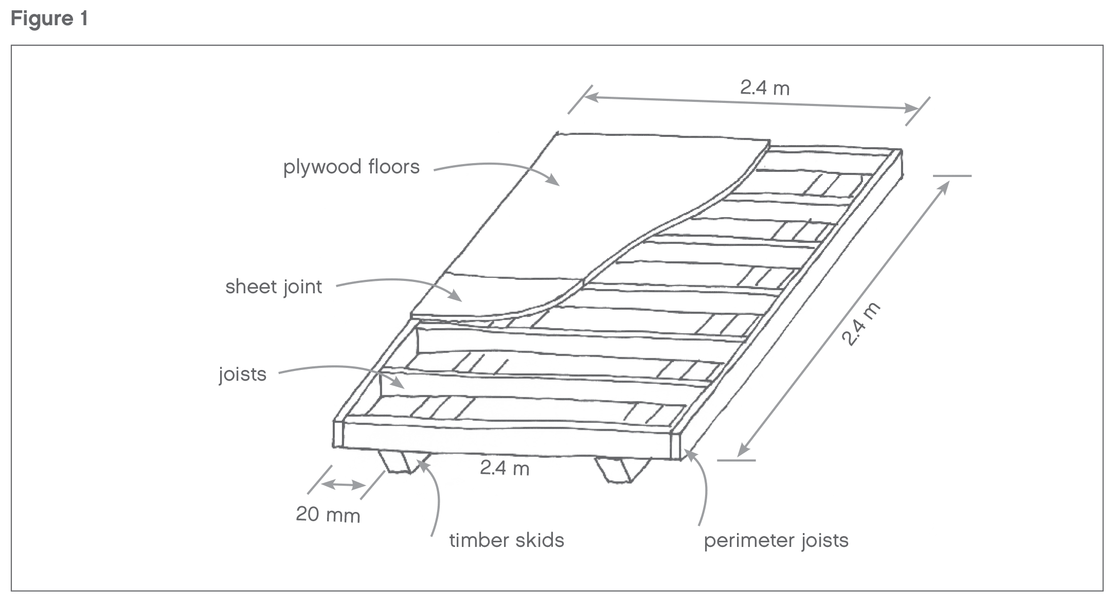
Cut five lengths of 100 x 50 mm timber joists to 2.3 m in length and two joists to 2.4m in length. Nail a 2.3 m joist on edge between each end of the two 2.4 m joists with 100 mm jolt-head galvanised nails through the face of the 2.4 m joists into the ends of the 2.3 m joists, to form a 2.4 m square of joists on edge. Mark out the centre joist position to align with the joint in the plywood flooring and fix in place. Locate remaining joists equally spaced between the centre joist and end joists (400 mm centres approx.) to complete the floor (Figure 1).
Bearers/skids
Mark the joists 200 mm in from two opposite sides of the floor platform, to a line at right angles to the joists. Cut two 2.4 m long 100 x 100 mm timber bearers with a 45º cut at each end. Skew nail them to the joists with 100 mm jolt-head galvanised nails each side of the bearer into each joist, along the marked line, to form skids that will allow the shed to be moved. Ensure that each end of the skids aligns to the edge of the perimeter joists, and that you have measured the diagonal dimensions of the platform and made adjustments until the dimensions are equal before you nail the bearers to the joists. This indicates that the platform is square.
Turn the joist platform over so that the skids are on the ground. Slide the platform to the desired location. To make the platform level, either dig ground away from under the skids or pack with a solid, durable material (Figure 1).
Floor
Lay one 2.4 x 1.2 m sheet of plywood parallel to the joists. Ensure that the platform is square by checking the diagonal measure, and that the edges of the plywood sheet align with the outside faces of the perimeter joists. Nail the sheet with 60 mm flat-head galvanised nails at 200 mm centres along the line of each joist and around the perimeter.
Fix the next plywood sheet in the same way, ensuring that it is cleanly butted to the nailed sheet and that it aligns to the edges of the perimeter joists. You will now have a 2.4 m square plywood floor platform on skids (Figure 1).
Side Walls

The walls of the shed are made up of two side walls, a rear wall with no openings, and a front wall with a window and a door. All walls are 2.085 m high with the roof rafters sitting on top of the walls (with a packer to form the fall).
To form each of the side walls, cut two 90 x 45 mm top and bottom timber plates at 2.4 m long and five 90 x 45 mm x 1.995 m long timber studs per wall. Mark the studs on edge between each end of the two plates and the other three studs at equal centres of 600 mm along the plates between the end studs. Nail the studs in place between the top and bottom plate with 100mm jolt-head galvanised nails through the face of the plates into the ends of the studs. You will now have two wall frames that are 2.4 m long by 2.085 m high (Figure 2). Ensure that the centre stud is positioned centrally on the wall for the plywood sheet joint.
Erect the side wall frames along each side of the floor platform, align them with the outside face of the perimeter joist and to each end of the platform and tack them in place. Install a temporary timber brace to each end of the wall, fixed down to the perimeter joist at the back and front of the platform. Nail off the braces when you have ensured that the walls are plumb. Nail the bottom plate through the plywood floor into the joists with 100 mm jolt-head galvanised nails at each end of the plate and next to each stud along the wall. Ensure that the wall frame remains aligned to the perimeter joists (Figure 2).
Rear wall
Measure the distance between the bottom plates of the side walls, across the rear of the floor platform. Cut a 90 x 45 mm timber top and bottom plate to this length and five 90 x 45 mm by 1.995 mm long timber studs. Nail the studs on edge between each end of the two plates and at equal centres of 600 mm along the plates between the end studs, with 100 mm jolt-head galvanised nails through the face of the plates into the ends of the studs. You will now have a wall frame that is 2.085 m high and the length of the rear of the platform (Figure 2). Ensure that the centre stud is positioned centrally on the wall for the plywood sheet joint.
Erect the rear wall frame along the rear of the floor platform, between the two side walls and aligned with the outside face of the perimeter joist and tack it in place. Align the wall at each end vertically with the side wall frames. Nail through the face of the rear wall end studs into the edge of the side wall end studs, with 100 mm jolt-head galvanised nails at top and bottom and at 200 mm centres in between. Nail the bottom plate through the plywood floor into the joists with 100 mm jolt-head galvanised nails at each end of the plate and next to each stud along the wall. Ensure that the wall frame remains aligned to the perimeter joists. You will now have 2.175 m high walls to three sides of the shed (Figure 2).
Front wall
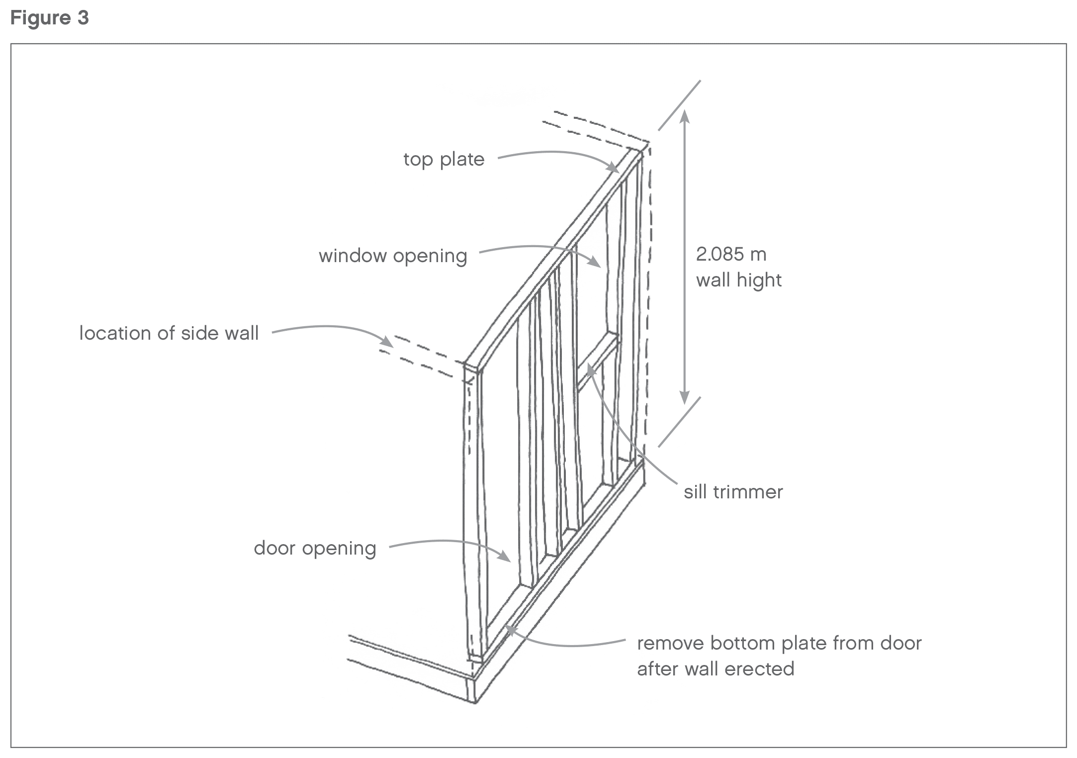
The front wall incorporates a window and a door. Measure the distance between the bottom plates of the side walls across the front of the floor platform. Cut a 90 x 45 mm timber top and bottom plate to this length and six 90 x 45 mm by 1.995 mm long timber studs. Nail one stud on edge between each end of the two plates with 100 mm jolt-head galvanised nails through the face of the plates into the ends of the studs, to form the ends of the front wall (Figure 3).
Position one stud at the centre of the wall where the joint in the plywood will occur. Position remaining studs to suit the width of the door and window. If you choose to use a differently sized door or window, you will need to adjust the frame opening sizes to suit.
For the 710 mm wide left-hung exterior panel door (pre-hung in a 20 mm timber reveal with an overall frame size of 2.030 mm high by 750 mm wide), the right hand stud (when facing the outside of the wall) will need to be spaced 760 mm away from the end stud (inside face measure). This is to allow the door to be fitted with a10 mm gap each side. Ensure the studs are plumb (Figure 3).
For the window with an overall frame width of 600 mm, the left-hand studs (when facing the outside of the wall) will need to be spaced 620 mm away from the left hand end stud (inside face measure). This is to allow the window to be fitted with a 10 mm gap each side. Ensure the studs are plumb (Figure 3).
Measure down the studs either side of the window from the underside of the top plate, and form a mark 820 mm below the underside of the top plate. Cut and nail a 90 x 45 mm timber sill trimmer. Install it on its flat, horizontally across to form the bottom of the window.
You will now have a front wall frame with a framed opening to the left for a door and a framed opening to the right for a window (Figure 3).
Putting the walls together
Erect the front wall frame along the front of the floor platform between the two side walls and aligned with the outside face of the perimeter joist and tack it in place. Align the wall at each end vertically with the side walls. Nail through the face of the front wall end studs into the edge of the side wall end studs with 100 mm jolt-head galvanised nails at top and bottom and at 200 mm centres in between. Nail the bottom plate through the plywood floor into the joists with 100 mm jolt-head galvanised nails at each end of the plate and next to each stud along the wall. Ensuring that the wall frame remains aligned to the perimeter joists. Do not nail through the bottom plate at the door opening. With a saw, cut through the bottom plate on both sides of the door opening, hard against the lintel studs, and remove the length of timber. You will now have four 2.085 m high walls to the shed (Figure 3).
Rafters
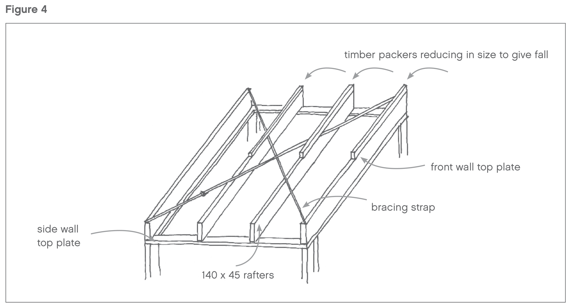
There are four rafters that span across the shed over the wall frames, where they are supported by, and fixed to, the side wall top plates.
Cut four 140 x 90 mm by 2.4 m long timber rafters and nail one rafter at the front and one at the back of the shed. The outside face of the rafters should be aligned to the outside of the wall frame and the ends of the rafters aligned to the outside edge of the side wall top plates. Skew nail the rafters to the top plates with 100 mm jolt-head galvanised nails either side of each rafter, and then nail the remaining two rafters at equal centres between the two outer rafters in the same manner (Figure 4).
Square up the roof frame by checking that the diagonal dimensions are equal. Nail lengths of galvanised steel flat strap brace in both directions across the top of the rafters on the diagonal of the roof, and nail the straps to each rafter with 60 mm galvanised flat-head nails (Figure 4).
The roofing iron needs to be set to a 75 mm fall from the front of the shed to the back. To create the fall, nail a length of 70 x 45 mm timber on its edge as a packer on top of the front rafter with 75 mm galvanised jolt-head nails, skew nailed into the rafter. Run a string line from the top of this packer to the top of the rafter at the rear of the shed and measure down from the line to the top of the two mid rafters. Cut packers to suit by ripping down lengths of 70 x 45 mm timber and nailing them to their respective rafters in the same manner as the first (Figure 4).
Cladding
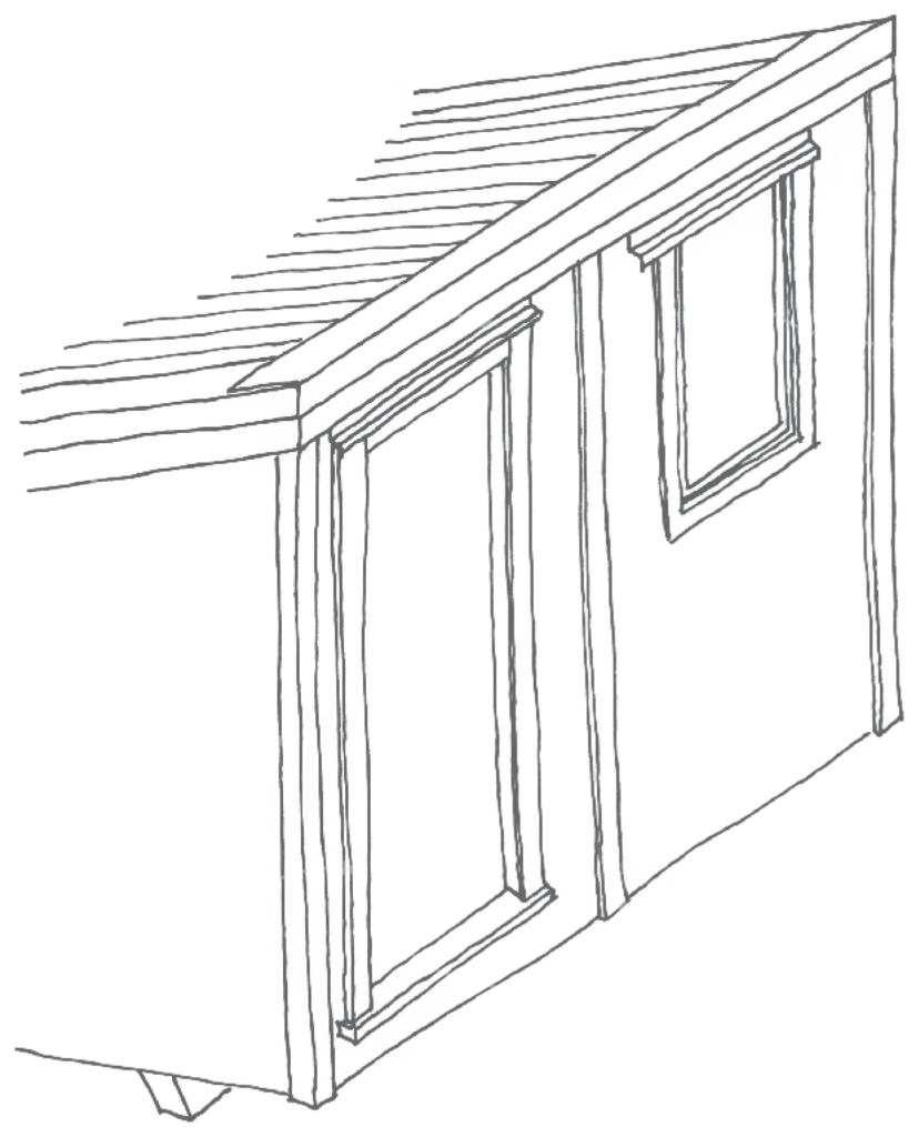
Clad each of the four walls by nailing 12 mm plywood sheets to the wall frames. Measure each sheet to its location and ensure that the bottom of the sheet finishes level with the bottom edge of the floor joists. The top edge of the sheet will need to be cut to an angle for the side walls and to length for the back wall. Trim the cladding around the openings for the door and window on the front wall. Vertical sheet joins should occur over studs and should be close-butted.
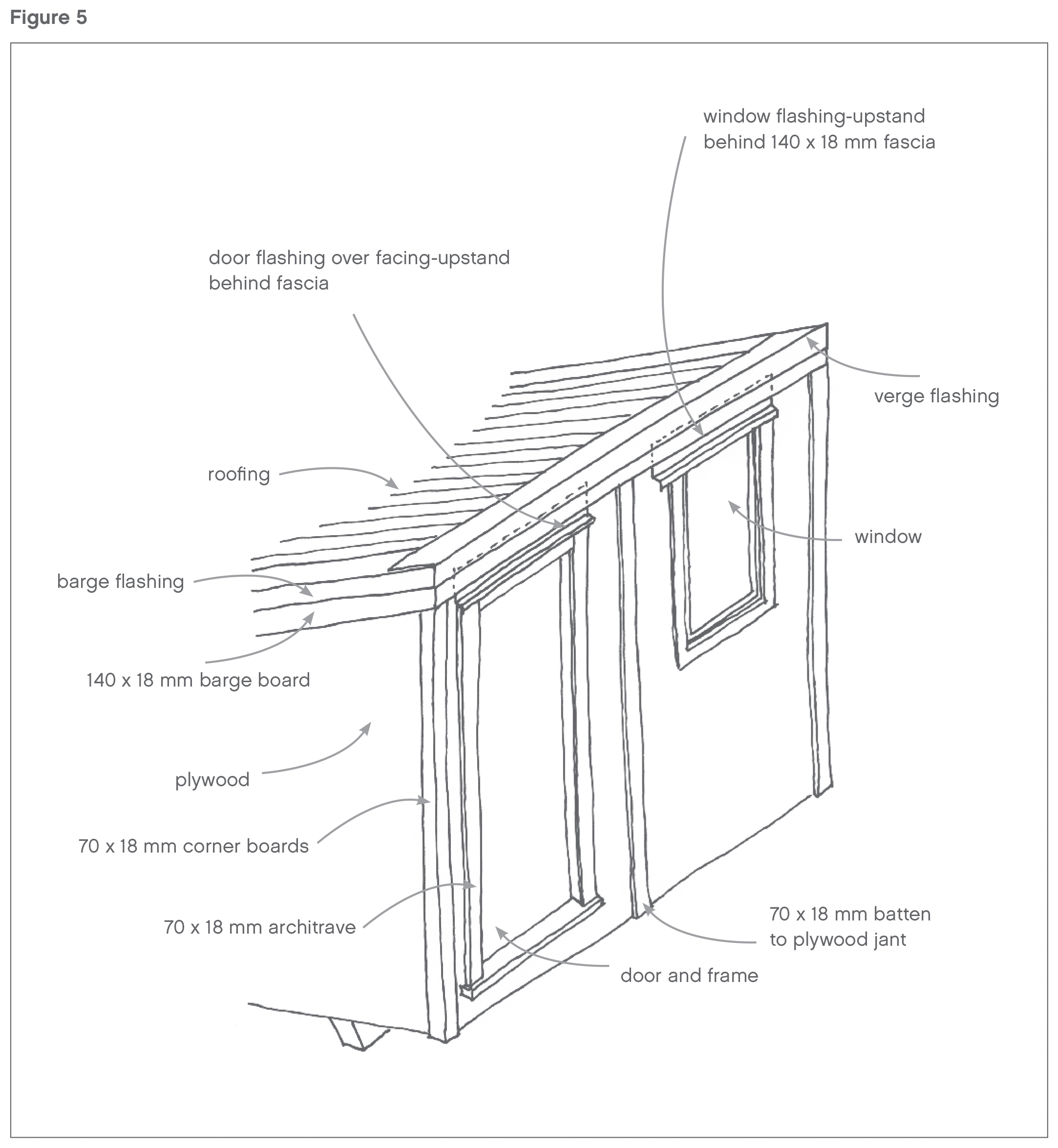
Nail the cladding to the studs with 60 mm galvanised flat-head nails at all sheet corners, at 300 mm centres around the sheet perimeter and at 400 mm centres up each intermediate stud (Figure 5).
Window
Insert the window into the opening – nail through the internal timber window reveal, into the wall framing with 75 mm galvanised jolt-head nails, using packers to the tolerance gap between the window reveal and the frame (Figure 5).
Install the head flashing with the upstand fitting behind the fascia board to the top of the wall. Ensure that it overlaps the window width by 30 mm each side. Install the window into the opening by angling the window head flange up under the head flashing and then pulling the window tight to the cladding.
Door
Install the door, pre-hung in a timber reveal, in its opening. Ensure that the timber door reveal is aligned to the face of the cladding on the outside and tack the door in place by nailing through the door reveal into the framing. Ensure that the door is installed true and opens and closes accurately, then permanently fix the door in place by nailing with 75 mm galvanised jolt-head nails through the timber reveal into the wall framing, using packers to the tolerance gap between the door reveal and the frame (Figure 5).
Install the door handle hardware.
Exterior trim
Fix the 140 x 18 mm fascia board to the top of the wall and fix the 70 x 18 mm battens to the external corners, over the plywood sheet joints and to the door frame as an facing (Figure 5).
Install the head flashing to the door with the upstand fitting behind the fascia board to the top of the wall.
Roofing

Measure and cut the selected durable metal roofing to the correct length. Allow for the roofing to lap as required and to align with the cladding at the front and sides of the shed and to overhang 100 mm at the back.
Install the galvanised netting to the roof structure over the top of the rafters/packers.
Lay the roof underlay, followed immediately by the roofing sheets. Fix in accordance with the roofing supplier’s instructions to the top of each rafter (Figure 6).
Install barge flashings over the roofing and down over the fascia to both sides. Install soft-edged verge flashing at the front of the roof and ensure a neat waterproof junction between the verge and barge flashings at each front corner (Figure 6).
Fix 70 x 18 mm exterior trim to the horizontal gap from the underside of the roofing to the cladding, where the roof overhangs at the back of the shed.
Local body bylaws may require the roof water to be collected and drained. If this is a requirement, you will need to install a roof gutter and connect this to drainage that complies with local regulations.
Alternatively, you may want to install a gutter and storage tank to collect the water.
Disclaimer
Refer to the New Zealand Standard for light timber frame construction, NZS 3604:1999 Timber framed buildings for more detailed information where your project varies from these instructions.
IMPORTANT INFORMATION FOR DIY BUILDERS
From August 2020, building consent exemptions were added to the Building Act for many types of low-risk building work, including sheds (under the Single-storey detached buildings category). Building work that does not require a building consent must still comply with the Building Code and other legislative requirements, such as those under the Resource Management Act 1991, the Electricity Act 1992 and the Health and Safety at Work Act 2015. Any issues related to planning or resource management, or any projects with district planning implications will still need to be discussed with your local council.
A shed built from the plans above would be exempt from requiring a consent, with these important provisions:
- It does not exceed 10 square metres in floor area (It does not – the plans above are for a shed with a floor area of 5.76 square metres).
- It does not contain cooking or sanitary facilities, or facilities for the storage of potable water (a potable water supply).
- It does not include sleeping accommodation, unless the building is used in connection with a dwelling and does not contain any cooking facilities.
- It is more than its own height away from all boundaries and the associated residential dwelling (in the case of these plans, a distance of 2.4m would suffice).
- It is not more than 1 storey (being a floor level of up to 1 metre above the supporting ground and a height of up to 3.5 metres above the floor level).
- The building materials, components and construction methods are sufficiently durable to ensure the building (without reconstruction or major renovation) satisfies the other functional requirements of the Building Code for the life of the building.
Here are the relevant documents to view on the government’s Building Performance website: